First Charge Custom Latch PCB
“If you solve enough problem, you get to come home”
-Mark Watney
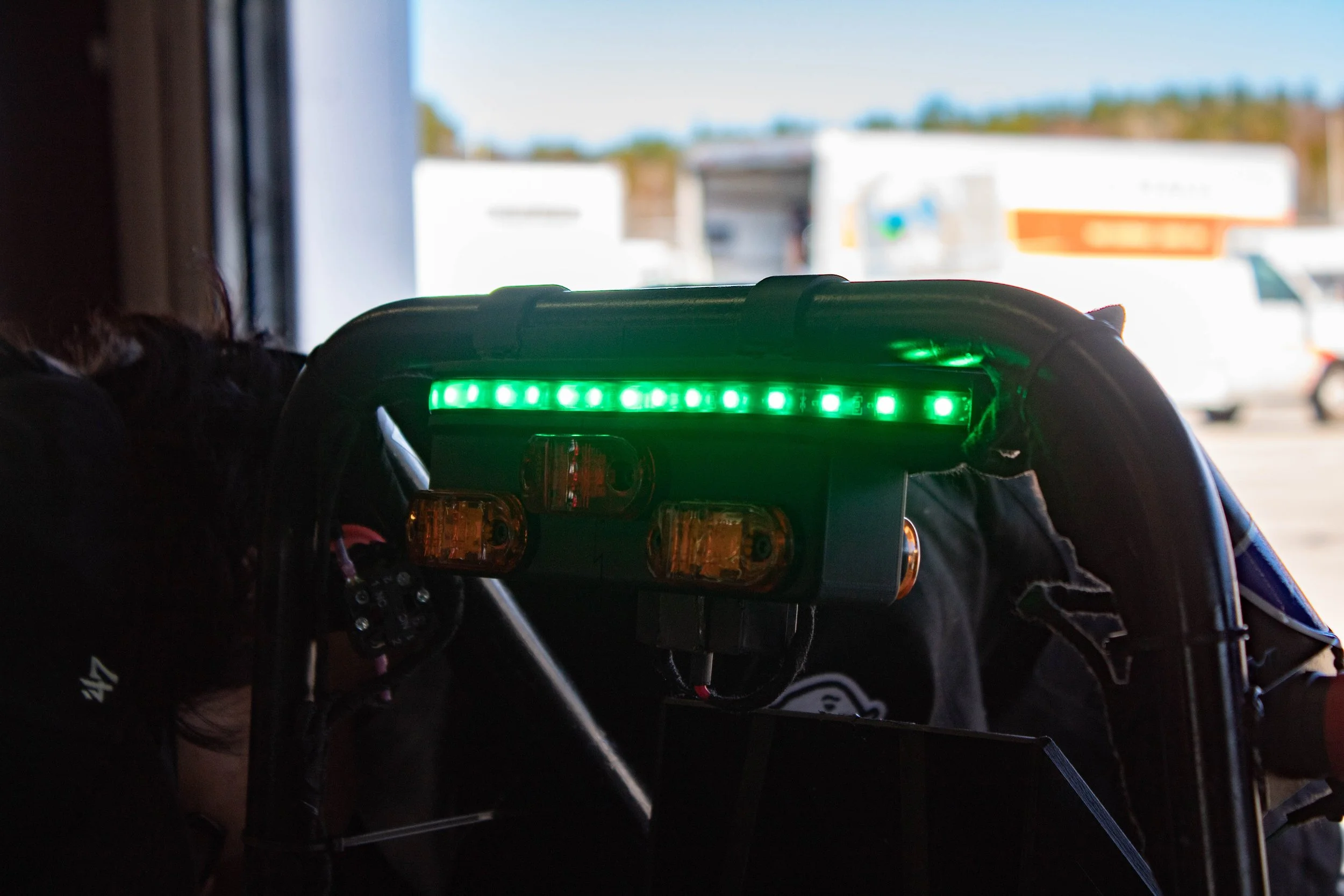
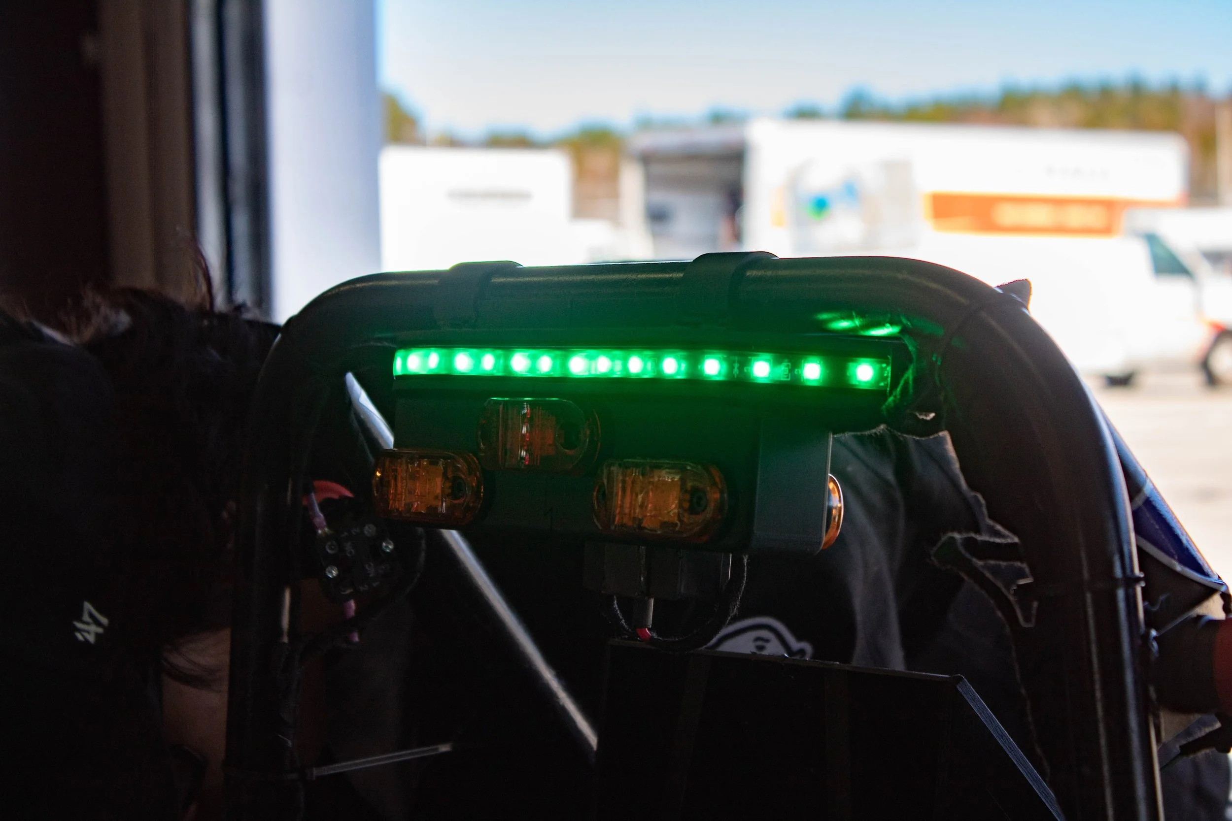
Photo by Raffaella Vogt
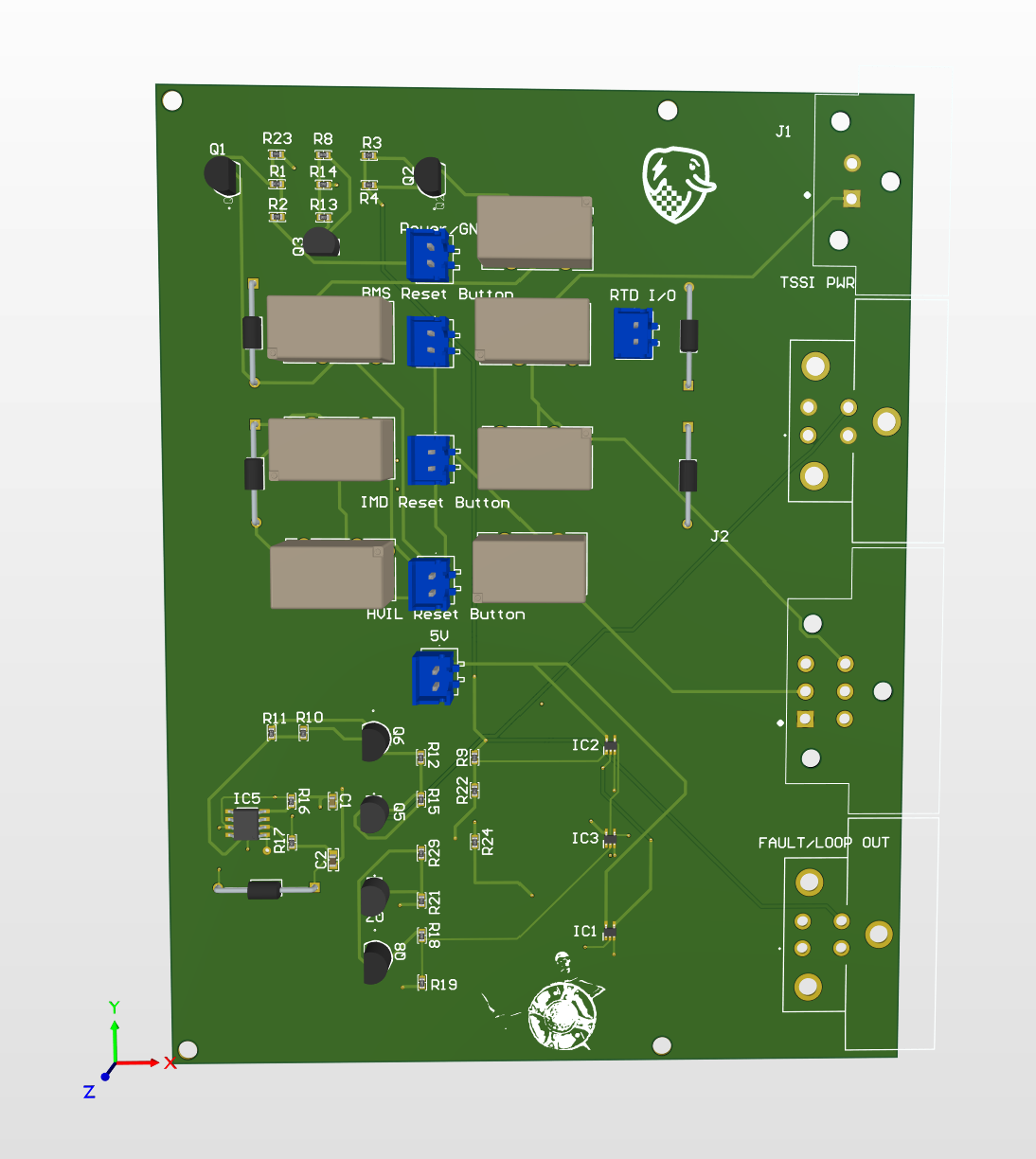
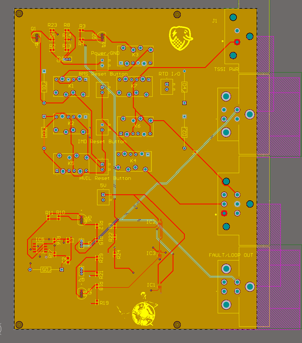
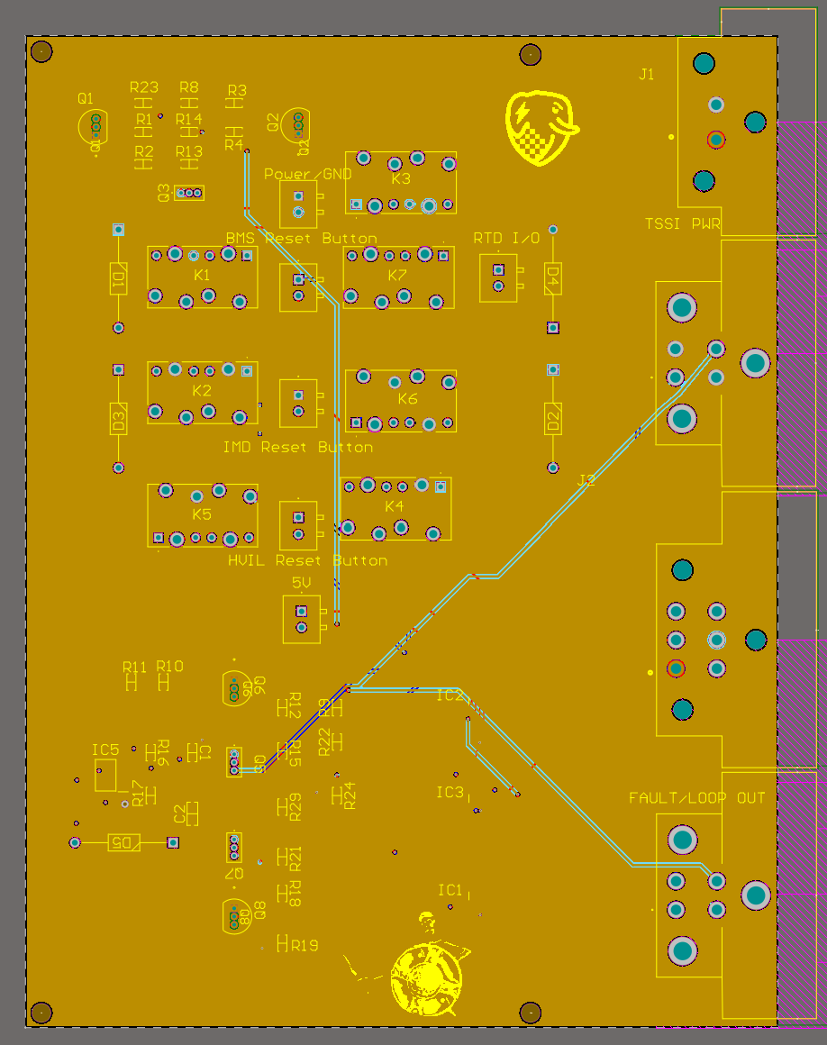
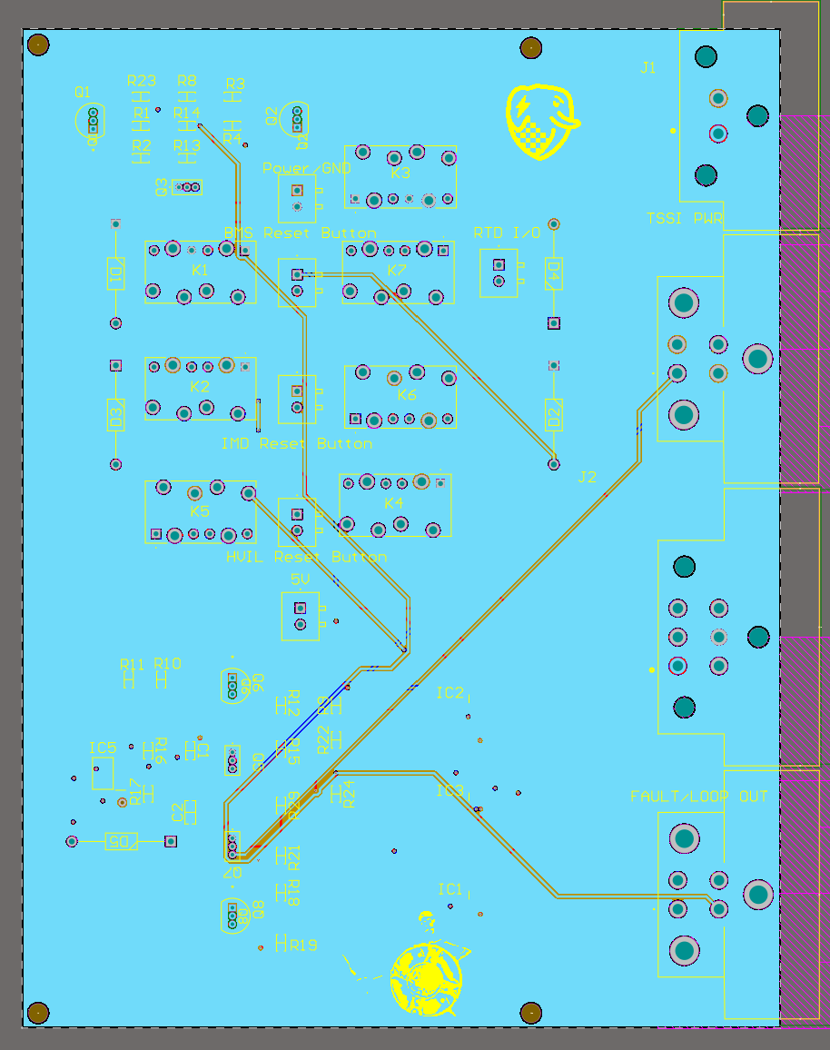
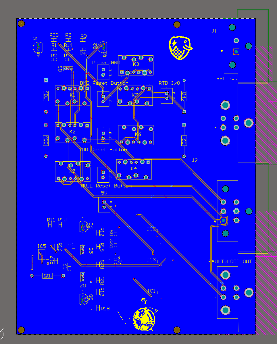
This is a board that was part of the GLV system redesign i did in 2025-26 for TER. It is a 4 layer board that handles the latching circuitry using electromechanical relays, TSSI logic, power and fault indicators. Made using Altium Designer
Year
2025-26
How it Works - Latches
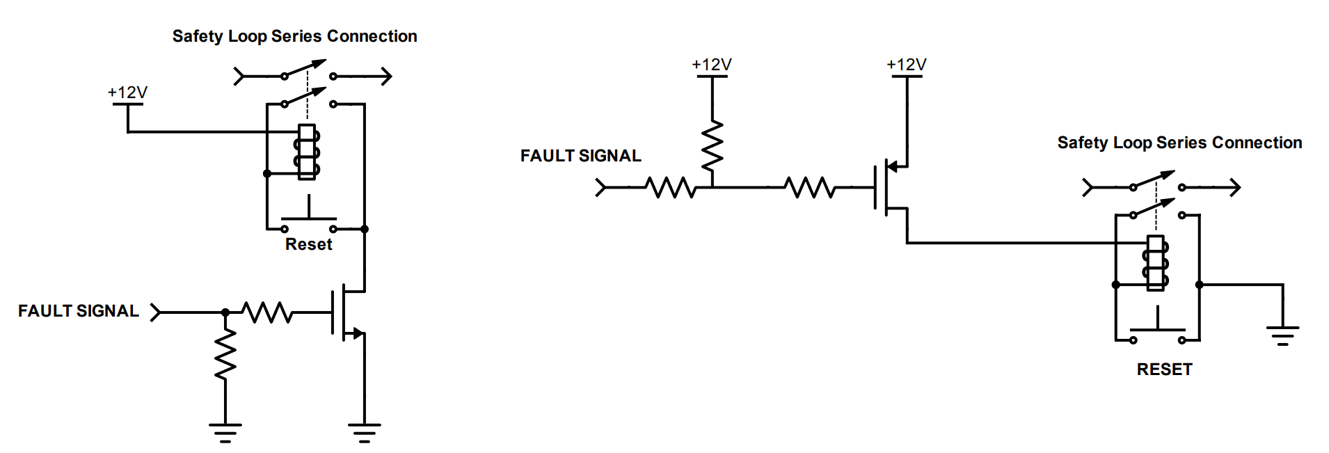
The latch circuit uses two relays to "remember" whether a fault has occurred on the car, holding the safety loop open until the fault is cleared and manually reset. The board includes two latch types: one where the fault signal is active-high, and one where it's inverted (active-low), to accommodate different fault sources.
Both Circuits are shown below
On power-up, the operator must press all latch reset buttons to close the safety loop. If no fault is present, the relay coil energizes and the switch contacts close, completing the loop. If a fault occurs, the coil de-energizes and the contacts open, breaking the loop — and they stay open until the fault clears and the reset button is pressed. Holding the reset button down while a fault is still present does not bypass this check; the relay will not re-latch until the fault condition is gone.
How it Works - TSSI
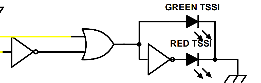
An addition to the rules that year was the Tractive System Status Indicator. A set of lights that convey whether any faults are present. Red flashing at any faults present, and green with none. This was achieved through logic gates controlling amplifiers to power on the lights corresponding to each status indicator. The flashing lights were achieved using a 555 Timer circuit controlling an amplifier.
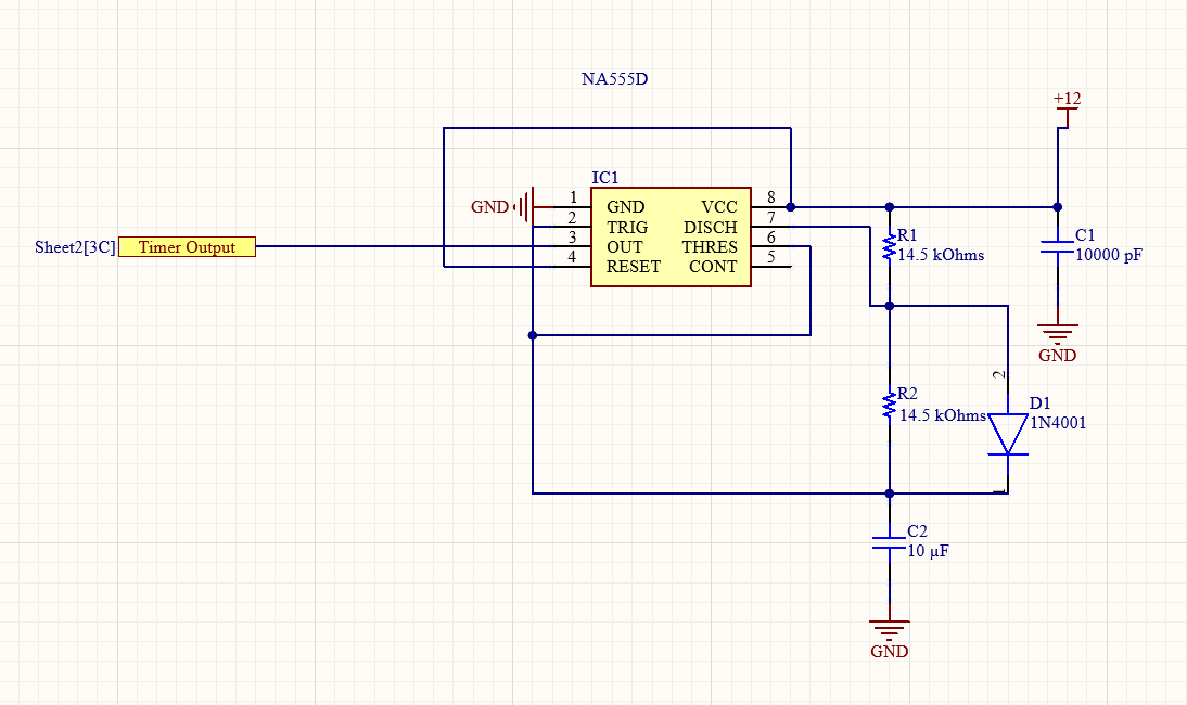
The logic system was created by using a truth table and Karnaugh Map to pick which gates to use. The board already gets input for faults, so there were additional paths created for the logic gates. The timer circuit was used according to the datasheet recommended circuits and layouts.