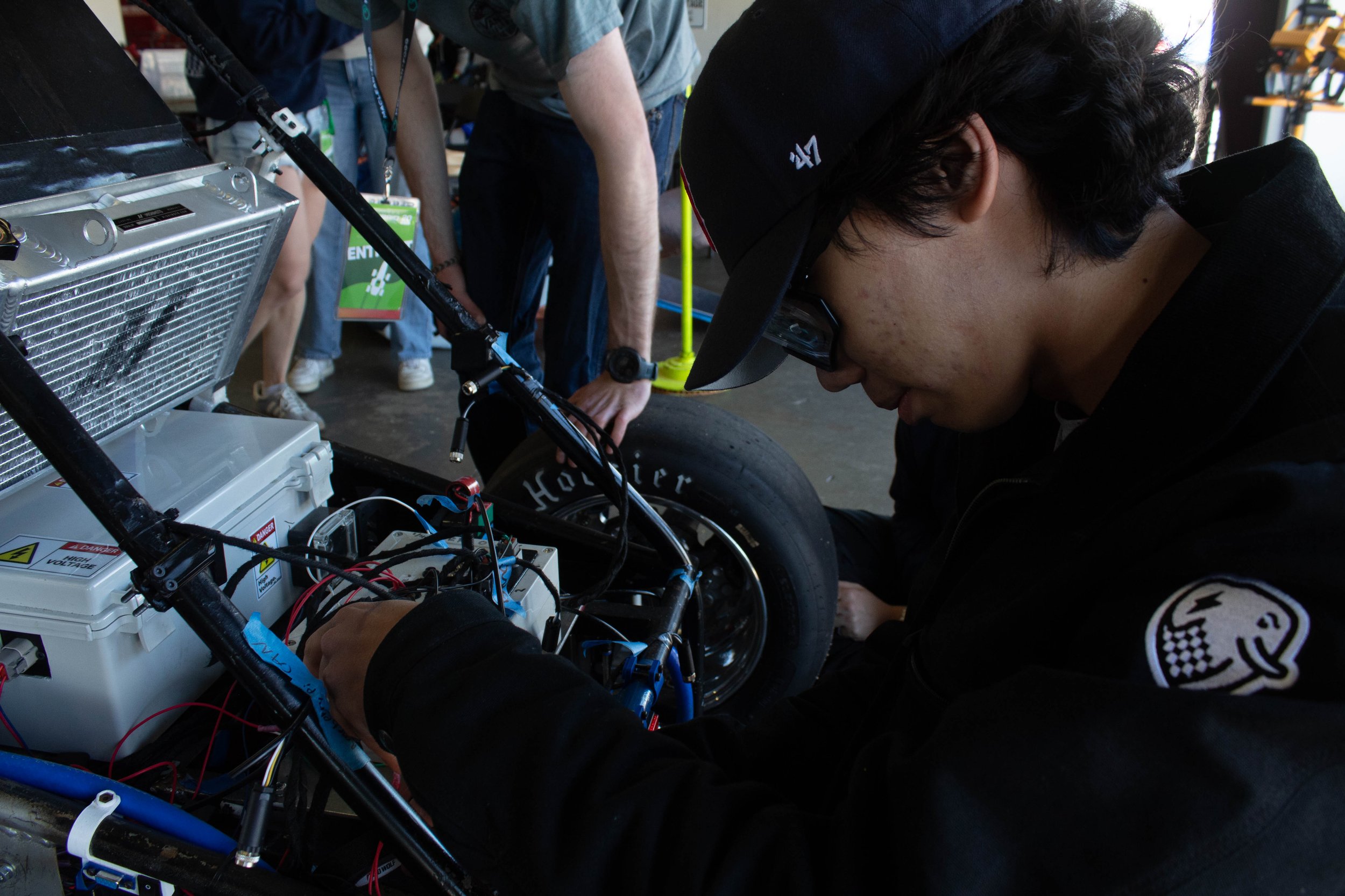
First Charge GLV System and Harness
"Grumpy. Angry. Stupid. How long since last sleep, question?"
-Rocky
Photo by Raffaella Vogt
I redesigned the Low Voltage system on the Tufts Electric Racing car as a project lead. Created custom PCBs using Altium Designer, and assembled the entire wiring harness.
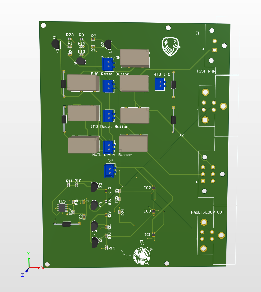
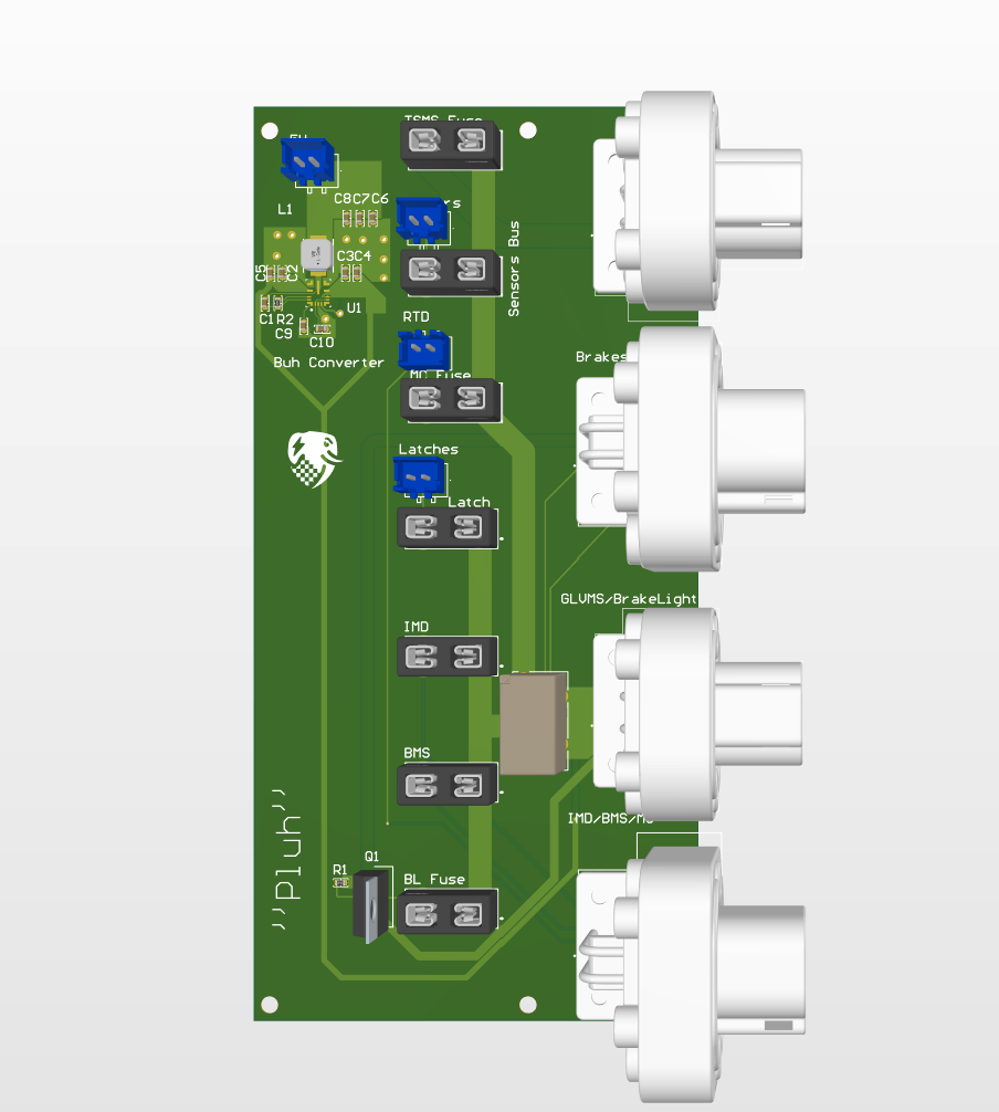
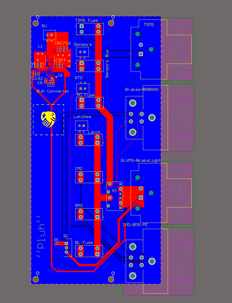
The project includes several custom PCBs for the latches, power distribution and fusing, dashboard indicators, and light strobing.
Year
2025-26
-
This project was all about reducing the amount of wires on the car. Condensing systems onto PCBs, and reordering how the GLV system connects was the primary focus.
-
Everything I did except the manufacturing process was my first experience with it. Learning the rules, the structure of critical safety systems, and designing PCBs were all things I had to learn on the fly.
Working under the pressure of hard deadlines (competition day) meant that there was little room for mistakes. Meaning that things had to be functional and clean with little revision.
-
I’ve learned a lot making this system, PCB design and manufacturing, wiring harness planning, and a lot of miscellaneous electrical knowledge. There are many things I would redesign if I were to take on this project again (less ground connections to the PCBs), but the system was functional with minimal altering, which was a pleasant surprise regarding the timelines with competition.
-
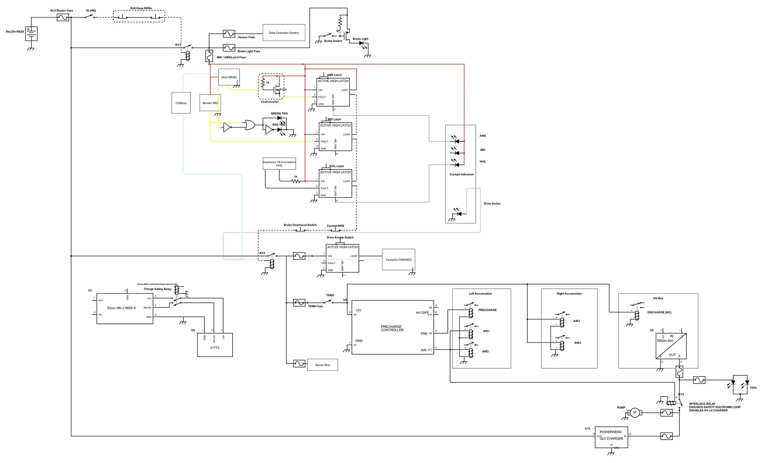
The safety loop (also called the shutdown circuit) is a series electrical circuit that must remain closed for the car to operate. It chains together every critical safety switch and sensor on the vehicle. This includes the master switch, shutdown buttons, battery management system (BMS) and insulation monitoring device (IMD) fault controlled latches, and the brake overtravel switch. If any part of the safety loop trips, the tractive system of the car will turn off. The master switch, shutdown buttons on the roll hoop, and the BMS/IMD latches will turn off the entire vehicle, and all the other shutdown circuitry will only turn off the tractive system.
-
There are 5 indicators on the car.
The latch fault indicators for the Battery Management System (BMS), Insulation Monitoring Device (IMD), and High Voltage Interlock (HVIL). These lights turn on when a fault is present in the corresponding latch system.
There is also the Tractive System Active Lamp (TSAL) an amber colored light that flashes when the Tractive System is on.
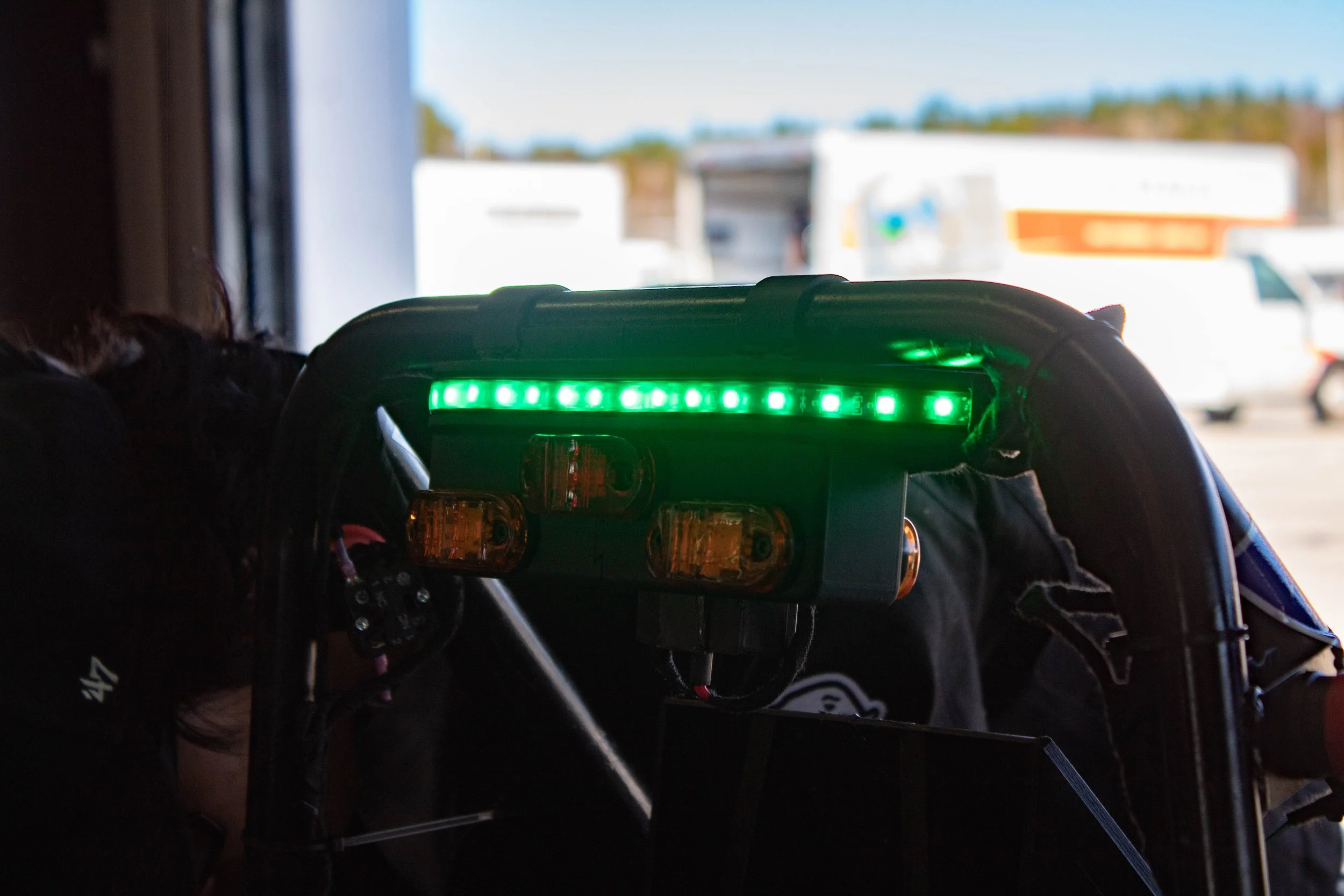
The 2026 FH+E rules added the Tractive System Status Indicator (TSSI), a rule borrowed from the FSAE Michigan rules. A green light for an “OK” status when no faults are present, and a flashing red light for when there are faults present in the BMS or IMD.
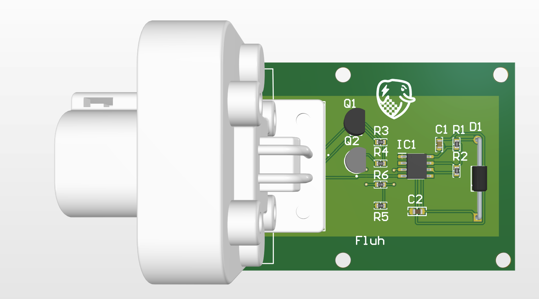
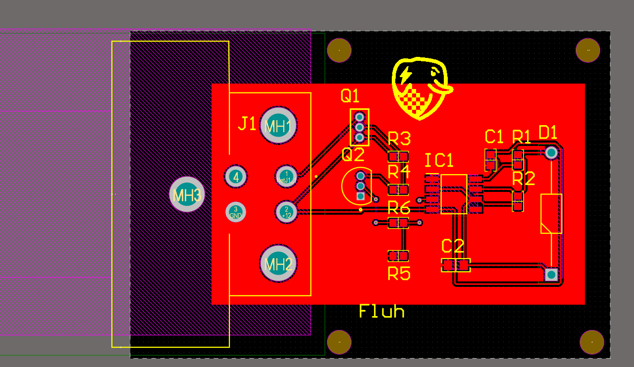
A custom light flashing board and mounts were made for this project.
-
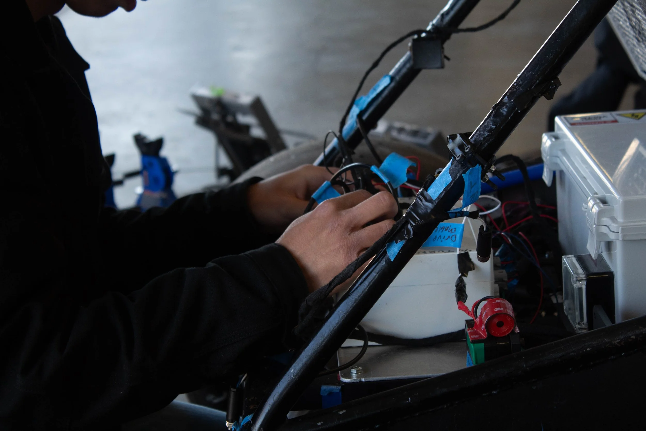
The goal for the redesign of the wiring harness was to reduce how many wires there are, and how many run the length of the car. The wiring was laid out primarily off the car and taped together with automotive harness tape, and Deutsch DTM connectors were used for PCB and harness connections. The layout of the safety loop and devices powered off of GLV make it so most things are located in the rear end of the vehicle, requiring only a few short wire runs to work.